Theory 2

Form Factor F

In the following figures simulated form factors |F(qy,qz)|2 for different shapes of objects are presented (log scale intensity). The scattering distribution in the patterns show, that one is able to distinguish between different form factors. By measuring the angle between the horizon and the scattering maxima in the case of, for example, a pyramidal shape one is able to calculate the angle of the side walls of the objects (figure 7). Due to the reciprocal space pattern, the real shape of all scattering objects is rotated by 90 degrees.

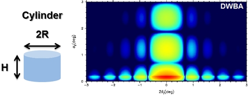
Figure 4: simulated cylindrical form factor (R=5nm; H/R=1)

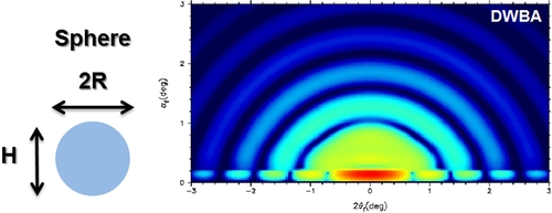
Figure 5: simulated spherical form factor (R=5nm; H/R=2)

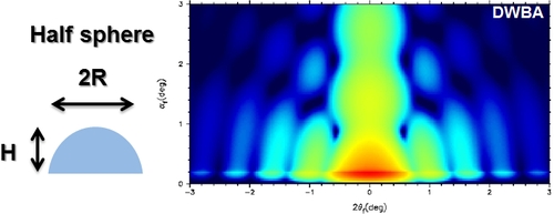
Figure 6: simulated half-spherical form factor (R=5nm; H/R=1)

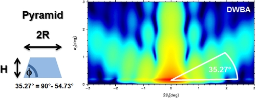
Figure 7: simulated pyramidal form factor (R=5nm; H/R=1; φ= 54.73°)

Interference Function S (structure factor)

In the case of arranged objects in a 2D-lattice, an interference function S along qy (parallel to surface) appears. For the case of upright standing hexagonal arranged cylinders, the interference pattern (figure 8) and the resulting combined form factor and interference pattern (figure 9) were simulated. Only where the combination of both scattering patterns (figure 4 and figure 8) rise to a maximum, a resulting scattering is observable.

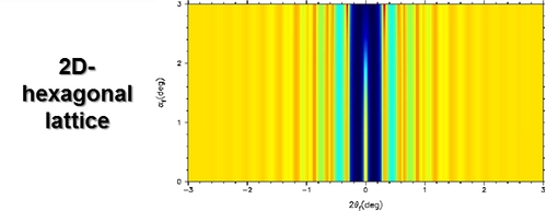
Figure 8: simulated interference function (2Dhex,a=20 nm)

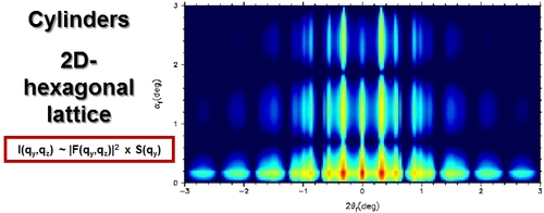
Figure 9:hexagonal arranged cylinders (R=5nm; H/R=1; 2Dhex,a=20 nm)

The same behaviour is observable in the following figures, which show the resulting scattering patterns for the same arrangement but different form factors:

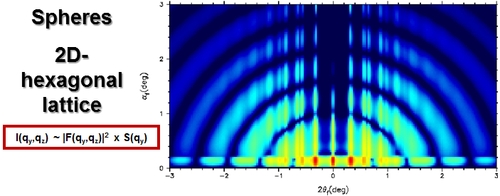
Figure 10:hexagonal arranged spheres (R=5nm; H/R=2; 2Dhex,a=20 nm)

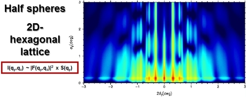
Figure 11:hexagonal arranged half spheres (R=5nm; H/R=1; 2Dhex,a=20 nm)

Contents provided by Dr. A. Meyer - Institute of Physical Chemistry - University of Hamburg