form and structure factors

Form Factor F
In the following figures simulated form factors |F
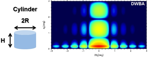
Figure 4: simulated cylindrical form factor (R=5nm; H/R=1)
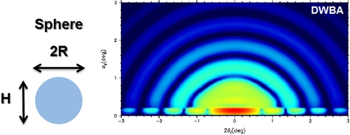
Figure 5: simulated spherical form factor (R=5nm; H/R=2)
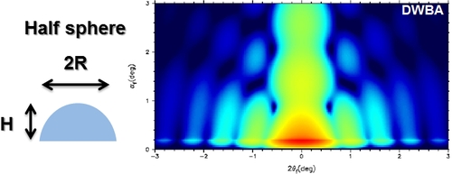
Figure 6: simulated half-spherical form factor (R=5nm; H/R=1)
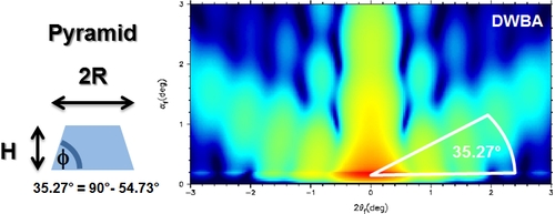
Figure 7: simulated pyramidal form factor (R=5nm; H/R=1; φ= 54.73°)
2D Interference Function S (structure factor)
In the case of arranged objects in a 2D-lattice, an interference function S just along q
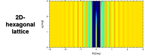
Figure 8: simulated interference function (2Dhex,a=20 nm)
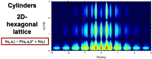
Figure 9: hexagonal arranged cylinders (R=5nm; H/R=1; 2Dhex,a=20 nm)
The same is observable in the following figures, which show the resulting scattering patterns for the same lattice S but different form factors F:
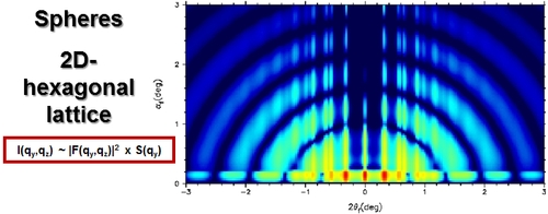
Figure 10: hexagonal arranged spheres (R=5nm; H/R=2; 2Dhex,a=20 nm)
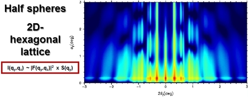
Figure 11: hexagonal arranged half spheres (R=5nm; H/R=1; 2Dhex,a=20 nm)
3D Interference Function S (structure factor)
When the investigated material is thicker (more "bulky") the function of the lattice becomes three-dimensional. Repeating distances in all spatial directions can take place and one has to calculate with lattice functions like in a normal tramsmission scattering experiment. The only difference is, that all 4 terms of the DWBA have to take into account, depending on the absorption of the material and the reflectance of the substrate. Normally, when the material is thick enough, only the incoming beam causes scattering and calculations are much easier and it is possible to the use simpler SAXS-equations with common S-functions for example like FCC, BCC, SC for spherical close-packed particles.