analysis

simple out-of-plane cuts to reveal 2D lattice information
For the analysis of several scattering patterns it would be annoying and time consuming to simulate full 2D-patterns by assuming different models. By analyzing so called out-of-plane cuts along qy, it is possible to analyze the interference function S(qy) for 2-dimensional arrangements directly. After extrating the scattering curve I(qy) at a constant qz where the scattering has suffentiently strong scattering (normally at the Yoneda peak of the substrate), one can feed the information in a general SAXS-analysis software. The following example show a 2D-hexagonal arrangment of iron oxide nanoparticles with a spherical shape. As the particle are dense packed in a monolayer and large enough to reduce scattering terms from the reflected beam at the substrate, only the first term of the DWBA plays a role. Here, at the Yoneda-maximum, a horizontal out-of-plane cut were extracted to get a scattering curve. As the 2D lattice function is independant to the qz postion where the horizontal cut was done, one can directly analyze the lattice type and size ot of the maxima in the curve. For the form factor of the particles instead, one has to take the qz position of cut into account, as the center of the concentric oscillation is the direct beam! When form factor information and precise fitting of the curve is needed (like shown in the example), one has to use special GISAXS software. In the example also diffraction from parts of thicker material appear (at edges of the substrate a FCC lattice is formed) and is visible around the primary beam, even below the sample horizon (marked as a hexagon).
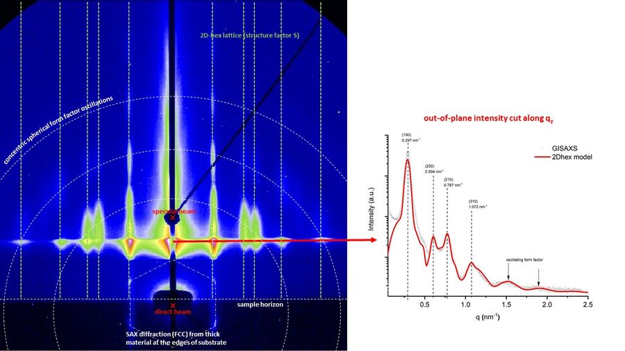
Figure 12: 2D-GISAXS pattern of spherical nanoparticles and out-of-plane cut along qy
analyzing 3D lattice information
When the investigated layer or film is thick, the regular arrangements are 3-dimensional. Here, one can use the simpler models of a a normal SAXS experiment, because only the first term of the DWBA (incoming scattering vector) take place. q=0 is the position of the direct, not reflected beam o the detector, which is normally behind the sample horizon (see Figure 3). That means that only the part above the sample horizon of the SAXS scattering pattern is detectable. Here, one use normally incident angles close to zero, where the beam is almost parallel to the investigated layer.
form factor analysis
The same rules are important for the form factor F. When the film is thin, one has to taken the full DWBA into account to get the precise shape of the scatterer. This is easy to understand, when looking at the simulated patterns (Figure 4 - 7). When making 1D-cut through the pattern, it depends strongly at which qz value the cut was made. Herefore, specialized GISAXS software is the right choice. Refer Links-section for information.